Innovative Commercial and Industrial Heat Transfer Solution Providers

Heat Transfer Solution Mastery
Home / All / Heating & Cooling Coils /
Precautions for the selection of dry coils and their application in clean air conditioning systems
Precautions for the selection of dry coils and their application in clean air conditioning systems


| Categories | Heating & Cooling Coils |
|---|---|
| Brand | Boyi Heat transfer industry support customization |
| Model | BY-DCC |
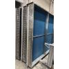
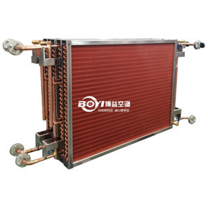
| Core Component | Finned tube heat exchangers |
| Tube Diameter | 7mm, 9.52mm, 12.7mm, 15.88mm |
| Casing Material | Galvanized Steel, Aluminium, Stainless Steel |
| Tube Material | copper, stainless steel |
| Fin Material | aluminum, copper, stainless steel |
| FOB port | guangzhou |
| Terms of Payment | L/C, D/P, Western Union, MoneyGram, T/T, Paypal |
| Update Time | Jul 1,2025 |
Detail Information
Definition:
The inlet water temperature of the dry coil is generally about 2 degrees higher than the dew point of the indoor air (inlet 13°C, outlet 18°C). The air velocity through the dry coil should preferably be 2 meters per second for optimal heat exchange efficiency. It is advisable to install a condensate drain pan to prevent condensation in cases of high humidity or inadequate pipe insulation. Dry coils are primarily used in cleanroom constant temperature and humidity air conditioning systems, which typically consist of three components: MAU (Make-up Air Unit), FFU (Fan Filter Unit), and DC (Dry Coil).
Dry Coil (DC) plays a critical role in the constant temperature and humidity air conditioning system of cleanrooms, and its application is closely related to the collaborative operation with other components (MAU, FFU) within the system.
System composition and functions:
1. MAU (Make-up Air Unit):
Function: Responsible for introducing and treating outdoor fresh air by removing particulate matter through primary and medium-efficiency filtration, and adjusting the air to specified temperature and humidity levels (typically close to indoor conditions) via heating, cooling, humidification, or dehumidification.
Core mission: To handle the system's latent heat load (humidity control) and ensure a constant humidity level in the air supplied to the cleanroom.
2. FFU (Fan Filter Unit):
Function: Installed in the cleanroom ceiling, it incorporates high-efficiency filters (HEPA/ULPA) to maintain cleanliness (particulate control) by continuously circulating indoor air, while establishing stable vertical laminar or turbulent airflow patterns.
Core mission: Ensure air cleanliness and airflow uniformity, without involvement in temperature and humidity regulation.
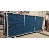
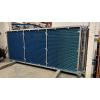
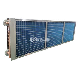
3. DC (Dry Coil):
Function: Installed in the return air plenum of a cleanroom or below FFUs, it regulates air temperature by circulating chilled or hot water, handling only sensible heat loads (temperature control) without dehumidification or humidification.
Core mission: To handle indoor sensible heat loads (such as equipment heat generation and occupant heat dissipation) and achieve precise temperature control.
The core advantages of dry coils:
1. No-condensate design:
1.1 Traditional cooling coils produce condensate due to their surface temperature being lower than the air dew point, which can easily breed bacteria and contaminate clean environments.
1.2 The dry coil controls the chilled water temperature (above the dew point of the return air) to prevent condensation, eliminating the risk of microbial growth at the source and complying with cleanroom standards such as ISO 14644.
2. Humidity and temperature decoupling control:
2.1 MAU focuses on humidity: handling the latent heat load of fresh air through deep dehumidification or humidification.
2.2 DC focuses on temperature: Only regulates sensible heat load, avoiding mutual interference between temperature and humidity control, thereby improving system stability and energy efficiency.
3. Flexibility and energy efficiency:
3.1 Dry coils can be zoned and independently controlled to address localized heat load variations (e.g., in areas with high heat-generating equipment).
3.2 The separation of sensible heat load and latent heat load reduces reheat/recool energy consumption and lowers operating costs.
The working principle of system collaboration:
1. Airflow path: The MAU-treated fresh air mixes with part of the return air, then is filtered by FFUs before being supplied to the cleanroom → The indoor air is cooled/heated by dry cooling coils → It circulates back to the return air plenum, where it mixes with the supplemental fresh air again.
2. Control logic:
2.1 Humidity control: The MAU adjusts the humidification/dehumidification volume based on the humidity sensor.
2.2 Temperature control: The dry coil adjusts the chilled water flow rate or temperature based on the temperature sensor.
2.3 Cleanliness control: FFUs operate continuously to maintain the air change rate (e.g., ISO Class 5 cleanrooms require ≥300 air changes per hour).
Typical application scenarios:
1. Semiconductor manufacturing: Requires extremely precise control of temperature and humidity fluctuations (±0.1°C/±1%RH) and particulate contamination. Dry coils are used to prevent condensate water from contaminating the wafers.
2. Biopharmaceutical: In a sterile environment, the dry coil's water-free characteristic complies with GMP standards.
3. Precision electronic assembly: Preventing static buildup caused by humidity fluctuations while ensuring precise temperature control to maintain equipment accuracy.
Design considerations:
1. Chilled water temperature setting: It should be higher than the dew point of the return air to avoid condensation. Typically, the chilled water supply/return temperature is 16°C/21°C (specific values need to be calculated based on indoor operating conditions).
2. Airflow organization optimization: The installation position of dry coils should be coordinated with the FFU layout to avoid temperature stratification or localized overheating.
3. Maintenance accessibility: Dry coils require regular dust removal (although there is no condensate, particles may accumulate), and maintenance access should be reserved during design.
The dry coil system has become the preferred solution for high-tech industries such as semiconductors and pharmaceuticals by maintaining the stringent requirements of cleanroom environments while achieving a balance between high energy efficiency and low contamination risk.
Key points in dry coil design:
1. The face velocity of the fin design should not exceed 2.5 m/s:
When the fin thickness direction of the DCC exceeds three rows of tubes and the air velocity is too high, the air resistance will exceed 30 Pa. If the temperature in the cleanroom is relatively high and the relative humidity is too high, condensation will form on the DCC, and excessive air velocity may cause water droplets to scatter.
2. The design fin wind speed should not be lower than 0.6 m/s:
Low wind speed results in poor heat transfer efficiency, which is not cost-effective. Additionally, it may lead to laminar airflow, hindering air mixing and causing uneven temperature distribution. Airflow allocation becomes uneven, with higher velocity in the middle of the finned tube heat exchanger and lower velocity at the top and bottom.
3. The flow velocity inside the finned tube should not exceed 1.8 m/s:
The water resistance in the pipeline exceeds 50 kPa, resulting in an excessively high head of the main water pump, increased pump power, and excessive water pressure in the pipeline. Water hammer occurs when starting without venting, causing damage to the DCC.
4. The flow velocity inside the finned tube should not be lower than 0.8 m/s.
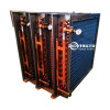
5. The inlet and outlet pipes require a quick-connection method.
6. The water inlet pipe is equipped with a drain valve, and the outlet pipe is provided with manual venting and operational exhaust devices.
7. The internal circuit requires an evacuated configuration and a full counterflow mode.
8. The special environment requires anti-corrosion and anti-static measures.
9. The installation method is simple and quick, requiring minimal fixation.
10. The class 1,000 cleanroom requires large cooling capacity with low air volume, necessitating a large temperature difference, while the class 100 cleanroom demands high air volume with small cooling capacity, requiring a small temperature difference.
11. The DCC water supply temperature must be higher than the indoor dew point temperature.
12. The surface air velocity of DCC in the same area must be designed to be identical, and the air resistance of the DCC must also be the same.
13. To ensure a service life of over 5 years, the heat exchange tube diameter of the DCC coil must be greater than 12.7 mm, with a wall thickness exceeding 0.45 mm.
14. To ensure installation quality, all DCC must maintain a pressure of 3–7 kg/cm, and the pressure holding time must exceed 48 hours. Afterward, on-site verification is required to confirm there is no pressure leakage.
- Specifications can be tailored to suit each application, with different materials, sizes, noises and cooling mediums available.
- contact us
Review
- Loading...
Related Products


Please send your message to us
- Tel
- *Title
- *Content